If this is your first visit, be sure to
check out the FAQ by clicking the
link above. You may have to register
before you can post: click the register link above to proceed. To start viewing messages,
select the forum that you want to visit from the selection below.
Speed3.5 - What are you doing about your ABS? My plan was to leave the stock ECU in to control it and run the MS as a standalone for everything else. Do you know if this will work? Will the ECU look at wheel speed sensors when its not got any other signals coming in?
Just added MS3X information, for those looking to run the MS3X on a Probe. This'll let you add sequential injection, six cylinder coil on plug, VRIS, fan, and A/C control, and still have enough I/O left over to add a progressive nitrous system or speed-based boost control.
Last edited by Matt Cramer; October 7, 2010, 09:13 AM.
This is not our preferred method of installing it since you would need to add a VR conditioner to use the crank trigger. It could be used with a '93-'94 distributor, or you could add a VR conditioner board.
I'll be glad to help anyone looking to set up a V2.2 on these cars, but it's unlikely to be added to the write-up on our website as I'd consider using a V2.2 for a new install a false economy.
Yeah I have a 2.2 left over from my se and would like to use it for my gt it's a 93 so what exactly do I have to do? We can do this thru pm if u would like
Matt, I am ready to do my coilpack from the mustang v6 EDIS6. I have the DIYPNP V1.1 with the latest firmware. It ran fine with the stock ignition until I burned it(stock internal coil pack) out. Switched to HEI+stock ecu for now. But ready to wire this edis6 in. Need step by step directions.
What I have:
36-1 Crank pulley off a Mazda 626 V6 98-'02
EDIS6 coilpack
3 BIP's already soldered to the board in their respective spots(S1,S2,S3)
Please provide me with step by step directions on tunerstudio settings, hardware mods if any for my diypnp board, how i can keep my stock tach and working, if any resistors needed on the coilpack rpm signal, etc. Any little detail at all will help. I'm tired of stock disty dying, and hei mod not working well with megasquirt.
Any help at this point is greatly appreciated by Matt or anyone else with a DIYPNP for the probe/mazda KL running coilpack setup.
1995 Ford Probe GT, black - Garrett GT3076-R @ 11.2psi. ~321ish whp/303ish wtq @ 19-20○ ignition, DIYPNP MS2/extra, etc. -parted & junked 1995 Ford Probe GT, black - MS3-Pro Ultimate, bone stock-ish, daily driver)
Matt, I am ready to do my coilpack from the mustang v6 EDIS6. I have the DIYPNP V1.1 with the latest firmware. It ran fine with the stock ignition until I burned it(stock internal coil pack) out. Switched to HEI+stock ecu for now. But ready to wire this edis6 in. Need step by step directions.
What I have:
36-1 Crank pulley off a Mazda 626 V6 98-'02
EDIS6 coilpack
3 BIP's already soldered to the board in their respective spots(S1,S2,S3)
Please provide me with step by step directions on tunerstudio settings, hardware mods if any for my diypnp board, how i can keep my stock tach and working, if any resistors needed on the coilpack rpm signal, etc. Any little detail at all will help. I'm tired of stock disty dying, and hei mod not working well with megasquirt.
Any help at this point is greatly appreciated by Matt or anyone else with a DIYPNP for the probe/mazda KL running coilpack setup.
Ok, you won't need the 36-1 crank trigger unless you really want to put it on there. Here are the mods you will need.
1. Put a 100 ohm resistor in the R2 slot in the 5 volt position.
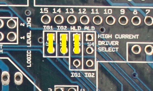
2. Solder on these jumpers.
3. Wire S1, S2, and S3 to the DB15 on the top row. Wire the DB15 to your coil pack. The spark outputs are S1 is spark A, S2 is spark B, and S3 is spark C.
4. Wire the Tach pin to the DB15 and from there to your dash tach.
5. Change the settings under Tach Input / Ignition Settings from Single Coil to Wasted Spark.
ok so after checking my board i have spark output set up on led17
i have read about the vr input circuit do i need to make one and a second trigger circuit or two vr circuits?
what pins do those connect to?
im assuming the circuit goes between the car harness and megasquirt. am i correct?
any mods for the spark out?
thanks for any help you can give
EDIT:looks like a zeal daughterboard has everything i need or is this overboard
For the spark output, wire a 270 to 330 ohm resistor from the negative (top) lead of D17 to the right lead of R23. Then run a wire from the negative lead of D17 to your ignition module.
You will need a LM1815 or similar circuit to read the crank trigger. I would go with a Zeal Engineering Daughterboard for this; it would also give you some relay control circuits for the VRIS and fans. Remove the Hall / optical input circuit, bring VR1 in on the unbanded side of D5, and bring the Zeal board's VR output to the bottom end of R11.
For the second trigger:
1. Solder a 1K resistor-on-a-wire from a point where you can get the camshaft signal to pin 11 of the processor.
2. Connect a 470 ohm resistor from pin 11 of the processor to JP1 pin 8.
3. Connect a 0.1 uF capacitor from pin 11 of the processor to JP1 pin 7.
 Tweet
Tweet


Comment